
Protection functions are programmed during configuration. The device is programmed by using so called protection library. Protection functions are energized by electrical values obtained by digital filtration of analog signals received from protection transformers.
A typical CZAZ-GT protection set consists of the set of functions listed below:
| 87G | Generator differential |
| 87B | Power unit differential |
| 87T | Transformer differential |
| 51G | Overload/overcurrent protection of generator stator |
| 51Z | Against phase-to-phase generator faulst |
| 21 | Admittance-based power unit protection |
| 32 | Reverse power protection |
| 67 | Directional, against loss of load |
| 59 | Overvoltage of power unit |
| 40/27 | Loss of excitation |
| 81 | Over-/underfrequency |
| 24 | Transformer overexcitation volt per hertz protection |
| 46 | Negative sequence definite-time overcurrent protection |
| 46inv | Negative sequence inverse time overcurrent protection |
| 78 | Slipping pole protection |
| 59GN | Generator residual voltage protection |
| 64S | 100% of generator stator protection, 3rd harmonic based |
| 51N | Ground overcurrent protection of power unit |
| 51ET | Overload protection of excitation transformer |
| 51TT | Overload protection of step-up transformer |
| 64R | Earth fault protection of generator rotor |
| 49R | Rotor thermal overload protection |
| 50/27 | Against connection of unexcitated generator |
Protection functions are supported by logic circuits, which are designed using available measuring functions, Boolean operators and timers. It allows to configure advanced automation circuits, for example:
| Rated current In | 1A, 5A |
| Rated voltage Un | 100V |
| Rated frequency | 50Hz |
| Rated auxilliary voltage Up | 110V lub 220V DC 230V AC |
| Burden of current inputs | ≤1VA/input |
| Burden of voltage inputs | ≤0,2VA/input |
| Continuous thermal withstand of current inputs | 2,2In |
| Continuous thermal withstand of voltage inputs | 2Un |
| 1 sec thermal withstand of current inputs | 80In |
| Dynamic withstand of current inputs (10 ms) | 125In |
| Relay outputs data: | |
| Control outputs: | |
| Breaking capacity (DC or AC/50Hz) | 5A |
| Continuous contact carry | 5A |
| Signalling purposes outputs: | |
| Max. breaking capacity – resistive load | 0,3A |
| Max. breaking capacity – L/R ≤ 40 ms | 0,12A |
| Continuous contact carry | 3A |
| Operating temperature range | (268÷313)K/(-5÷40)°C |
| Relative humidity (with no condensation) | ≤80% |
| Ingress Protection degree | IP40 |
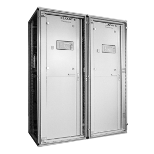
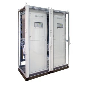
| Weight | (1 cabinet) ~250kg |
| Dimensions – (height x width x depth) | 2100 x 800 x 800 mm |
| Electromagnetic compatibility according to | EN 50263 |
| Insulation according to | EN 60255-5 |
Update your browser to view this website correctly.Update my browser now