CZAZ-UM/UM+
Digital protection and control relay for MV asynchronous and synchronous motor
Product description
Protection set
| 87 |
Differential protection for motors against internal faults |
| 50/51 |
Instantonous and definite-time overcurrent protection against phase-to-phase faults |
| 50/51 |
Overcurrent protection with option of 3 inverse-time characetersistics or definite-time |
| 50/51 |
Additional two overcurrent functions in order to fullfill busbar protection or breaker failure function |
| 51 |
Definite-time overcurrent dedicated to protect synchronous motor against loss of synchronism |
| 51N |
Ground fault overcurrent protection, inverse time characteristic |
| 67N |
Ground fault directional protection |
| 46 |
Current unbalance protection |
| 49 |
Thermal overload protection, two time constant thermal model |
| 48/66 |
Motor start-up supervision |
| 51LR |
Overcurrent, against locked rotor |
| 51 |
Overcurrent, against motor stall |
| 37 |
Undercurrent, against motor idle |
| 27/59 |
Under and overvoltage protection |
| · |
Three temperature inputs in 4-20mA loop to protect motor against overheat or to measure temperature |
| · |
Rotor cage supervision ensuring detection of failure of one bar or ring (only CZAZ-UM+) |
| · |
Cable insulation failure detector |
| · |
Arc Flash Detector |
TECHNICAL DATA
| Rated current In |
1A albo 5A |
| Rated voltage Un |
100V |
| Rated frequency fn |
50Hz |
| Rated auxilliary voltage Up |
110V or 220V DC |
| Burden in measuring inputs |
≤0,5VA/input |
| Burden in supply module |
≤25W |
| Pick-up time |
≤40ms |
| Continuous thermal withstand of current inputs |
2,2In |
| 1 sec thermal withstand of current inputs |
80In |
| Dynamic withstand of current inputs (10 ms) |
200In |
| Continuous voltage withstand of voltage inputs |
1,2Un |
| 10 sec voltage withstand of voltage inputs |
1,5Un |
| Relay outputs data: |
|
| Max. breaking capacity by U=250V DC |
|
| – resistive load |
0,3A |
| – L/R ≤ 40 ms |
0,12A |
| Max. breaking capacity by U=250V AC, 50Hz |
|
| -inductive load of cosϕ=0,4 |
3A |
| Continuous contact carry |
5A |
| Operating temperature range |
(263÷328)K/(-10÷55)°C |
| Relative humidity |
≤80% |
| Ingress Protection degree |
IP40 |
| Weight |
6,5kg |
| Dimensions (height x width x depth) |
|
| – surface mounting |
223 x 337 x 260 mm |
| – flush mounting |
288 x 145 x 305 mm |
| – metal enclosure – surface mounting |
337 x 223 x 260 mm |
| – metal enclosure – flush mounting |
298 x 256 x 258 mm |
| Electromagnetic compatibility according to |
EN 50263 |
| Insulation according to |
EN 60255-5 |
Main features
- Unified and universal hardware and software allowing adaption of the relay to protected objects
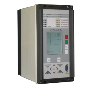
- Two realisations of HMI:
- graphic display for visualisation current bay state. It enables to simultaneously display: mimic diagram, several selected measured values and other states. Alphanumeric display also available
- 7” touch screen with resolution of 800 x 480
- specialised bay controller with biult-in logic to provide safe maintance of bay both in local and remote control mode. Proper control functions are coverd by continuous controlling of switch positions and blocking signals from protection functions. The relays cooperate with substation automation system. The functioning of switch control covers:
- Circuit breaker position and charging control – by 3 dedicated binary inputs
- Control voltage supervision
- Trip circuits supervision
- operational and test command for closing the circuit breaker
- operational and trip command for opening the circuit breaker
- position control of disconnector, earthing switch and changeover switch – whatever installed in switchgear bay
- Programmable bay controller with programmable logic which allows to add extra logic circuits and more complex protection circuits (busbar protection or breaker failure logic). Possibility to control bay switches (with proper blocking system of opening and closing commands). Programmable logic is set by simple and user friendly graphic interface:
- 21 binary inputs and 16 logic inputs controlled by communication port
- 14 output relays
- tens of signals generated by biult-in unit logic (pick-ups and trip signals from protection functions, faulty position of switches signals, substation control system signals, trip circuit supervision signals etc.)
- possibility to design user logical circuits and time delays using Boolean operators (AND, OR and NOT), multifunctional timers and other automation functions (eg. technological protection, auto-reclose automation, underfrequency load shedding). Possibility to display logic states on LCD, record in event recorder or send to remote control system
- Set of biult-in bay diagrams or possibility to build user custom bay diagram
- Output circuits allowing to direct control of bay switches, including two trip outputs with trip circuit supervision function
- 8 (CZAZ-U) or 11 (CZAZ-UM) analog inputs (phase currents, phase to phase voltages, residual current, residual voltage – CZAZ-U and -UM and set of currents for differential protection – only CZAZ-UM)
- Measuring of current electrical values (phase currents, residual current, phase or phase to phase voltages, residual voltage, active and reactive power, active and reactive energy in both directions, power factor)
- Recordings of disturbances and events:
- recording of approx. 150 unique events in memory of 500 records
- disturbance recorder saves 8 waveforms and 16 binary signals
- recording of maximum and minimum value of voltage, current or frequency and time of duration of last fault
- trips counter and sum of tripped currents counter
- Visual signalling (LED diodes) of key relay conditions (PWR, OK, TRIP)
- 8 or 16 user programmable LED diodes for signalling other logical values
- system of self control and autotest, signalling improper relay status
- screwless terminals for current inputs, pluggable terminals for other circuits
- communication with PC computer or SCADA system by RS 232/485 port or by fiber optic. Offered communication protocols: MODBUS RTU, MODBUS ASC, IEC 60870-5-103
You need more information?
Contact our Sales Department and talk to our expert about the details.