
| 51 | definite-time overcurrent protection |
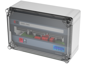
Overcurrent backup protection ODR-2WA is supplied by current transformer of secondary winding rated power of at least 25 VA. If controlled current exceeds the set value, the process of storing energy in capacitors starts. At the moment when capacitors voltage reach the required value (approx. 300 V for 220 V aux. volt. version or approx. 150 V for 110 V aux. volt. ver.) the relay starts its operation. The capacitors are galvanicly separeted and after set time-delay connected to CB trip coils.
Proper operation of relay is auxilliary voltage independent. That ensures tripping of faulted object even in case of lack of auxilliary voltage when primary protections fails to operate.
| Rated current In | 1 A, 5 A |
| Rated frequency fn | 50 Hz |
| Nominal auxilliary voltage Up | 110 V, 220 V DC |
| Setting range of threshold current |
0,5 A, 0,6 A, 0,8 A, 1 A, 1,3 A, 1,6 A for In=1A 2,5 A, 3 A, 4 A, 5 A, 6,5 A, 8 A for In=5A |
| Accuracy of current input | 10 % |
| Supports Circuit-Breakers of following specification | |
|
110 V DC or 220 V DC |
|
≤ 600 W |
|
≥ 80 Ω |
| Setting range of timer | 3 – 8 s for I > 1,3 Ir |
| Burden of analog inputs | ≤ 25 VA /input |
| Burden of auxilliary voltage supply | ≤ 3 W |
| Continously thermal withstand of current input | 2,2 In |
| 1 sec thermal withstand of current input | 80 In |
| Dynamic withstand of current input | 200 In |
| Trip outputs data | |
| Continuous contact carry | 8 A |
| Max. breaking capacity – resistive load | 0,3 A |
| Max. breaking capacity – L/R ≤ 40 ms | 0,12 A |
| Max. breaking capacity – for AC 250 V, 50 Hz | 3 A |
| Operating temperature range | -25 …. 55 ºC |
| Relative humidity (with no condensation) | ≤ 80% |
| Ingress Protection degree | IP40 |
| Weight | 10 kg |
| Dimensions (width x height x depth) | 300 x 200 x 135 mm |
| Electromagnetic compatibility according to | EN 50263 |
| Insulation according to | EN 60255-5 |
Update your browser to view this website correctly.Update my browser now