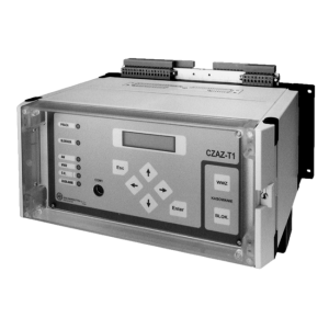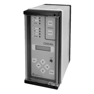


Depending on type of relay, different set of protection functions from the list below are implemented:
50/51 Instantonous and definite-time overcurrent protection against phase-to-phase faults
51 Definite-time or inverse time overcurrent protection
51/67 instanteneous or definite-time dedicated for long lines against phase-to-phase faults, with directional interlocking in CZAZ-L+ (67)
51/67 overcurrent against phase-to-phase faults with two possible operation modes:
– definite-time overcurrent with directrional interlocking
– inverse-time overcurrent
51N/27 inverse-time overcurrent against ground faults with option of interlocking by residual undervoltage
51N/67N against ground fault with option to choose one of the following operation modes:
– two-stages overcurrent (51N)
– inverse-time overcurrent (51N)
– directional overcurrent (67N)
– admittance-based directional protection
50N/51N ground overcurrent, definite-time, two-stages
51N ground overcurrent, inverse-time
21N admittance-based against ground faults protection
67N directional ground overcurrent
59N ground overvoltage
27 undervoltage, definite-time, two-stages
59 overvoltage
81 overfrequency
62 external
79 auto-reclose automation
Arc Flash Detector (optionally)
coordination with UFLS and AR after UFLS automation
coordination with transformer Bulcholtz protection
– CB failure function
– cooperation with ATS function
– Switch Onto Fault function
– cooperation with station failure/alarm signalling system
Cooperation with breakers function ensures:
– supervising of CB postition
– Trip Circuits Supervising functions
– Open command and Close command
– Disconnector and Earthing switch postion supervising
Up to 24 binary inputs and 10 relay outputs in order to fullfil functions listed above.
– 8 programmable relay outputs
– 5 binary inputs for cooperation with external protections
– 2 TRIP purposes relay outputs allowing to direct connection with CB coils and with Trip Circuit Supervision function
– 7 measuring inputs (phase currents, phase-to-phase voltages, residual current/voltage)
– Measuring of current electrical vaules (phase currents, zero-sequence current, phase-to-phase voltages, active power, reactive power, active energy counter, power factor)
– Event and disturbances recorders
– ab. 70 unique events register with capacity to memorise up to 500 events
– disturbance recorder of sampling frequency 1000 Hz (7 analog signals and 16 binary signals)
– parameters of last disturbance recorder: maximum current during disturbance and duration of disturbance
– number of protection operations counter and sum of tripped current counter
– optical visualisation of most important states of protected object (8 LED diodes)
– autotest and autocontrol system
– screw terminals for current inputs and pluggable screwless terminals for other circuits
– autonomic communication by local Human Machine Interface
– remote communication with PC computer or supervising system
Update your browser to view this website correctly.Update my browser now