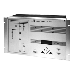
CZAZ-RR
HV switchgear protection relay
Product description
Protection set
| 50,51,51N |
Instanteneous or definite-time overcurrent |
| 51,51N |
Inverse-time overcurrent |
| 46 |
Negative-sequence overcurrent |
| 27 |
Undervoltage |
| 59 |
Overvoltage |
| 27/59/81 |
Frequency- and voltage-based protection |
| 21,21N |
Impedance-based protection |
| 81L |
Underfrequency |
| 81H |
Overfrequency |
|
|
| 32 |
Directional power-based protection |
| Standard configuration covers: |
|
| 67N |
ground fault directional protection, two-stages |
| 51 |
two-stages, overcurrent |
| · |
cooperation with Auto-reclose automation |
| · |
supervising and control of bay breakers including necessary interlocks (7 breakers supervised in two-bites manner) |
Main features
- 8 measuring inputs (phase currents and voltages, residual current, residual voltage)
- 35 binary inputs
- 3 TRIP purposes relay outputs allowing to direct connectrion with CB coils
- 21 programmable relay outputs
- Electrical values measuring (phase currents and voltages, frequency, active and reactive power, resistance, reactance, impedance, phase shift)
- Disturbance recorder (sampling frequency 1800 Hz)
- duration of recorded waveform up to 500s for one channel (ab. 10s for recording all 30 channels and 128 binary signals
- memory of 32 recording files
- recording of measured and calculated values
- Event recorder (capacity of 5000 events, 128 unique events, time resolution 1ms)
- Optical indication on front panel (15 LED diodes):
- bay failure
- trip
- device failure incl. supply module failure
- auxilliary voltage presence
- proper operation of the device
- 10 programmable diodes
- self test and self control system
- screwless terminals for measuring inputs, pluggable terminals for other circuits
- autonomic communication by local Human Machine Interface
- remote communication with PC computer or supervising system. Available communication protocols: MODBUS ASCII/RTU or MODBUS TCP/IP, IEC 60870-5-103
TECHNICAL DATA
| Rated current In |
1A or 5A |
| Rated voltage Un |
100V |
| Rated frequency fn |
50Hz |
| Auxilliary voltage Up |
110 or 220 V DC |
| Burden in measuring inputs |
≤0,5 VA |
| Burden in auxilliary voltage supply |
≤45W |
| Continuous thermal withstand of current inputs |
2,2In |
| 1 sec thermal withstand of current inputs |
80In |
| Dynamic withstand of current inputs (10 ms) |
200In |
| Continuous voltage withstand of voltage inputs |
1,2Un |
| 10 sec voltage withstand of voltage inputs |
1,5Un |
| Relay outputs data – TRIP purposes relay outputs: |
|
| by the voltage U=250V DC/AC |
|
| – inductive load of L/R=40ms |
3A |
| Continuous contact carry |
8A |
| Relay outputs data – other relay outputs: |
|
| Max. breaking capacity by U=250V DC |
|
| – resistive load |
0,3A |
| – inductive load of L/R=40ms |
0,12A |
| Max. breaking capacity by U=250V, 50Hz |
|
| – inductive load of cosϕ=0,4 |
3A |
| Continuous contact carry |
5A |
| Ambient temperature |
(268÷313)K/(-5÷40)°C |
| Relative humidity |
≤80% |
| Ingress Protection degree |
IP20 |
| Weight |
13kg |
| Dimensions (height x width x depth) |
|
| – rack 6U, 19” mounting |
265,9 x 482,6 x 262 mm |
| Electromagnetic compatibility according to |
PN-EN 50263 |
| Insulation according to |
PN-EN 60255-5 |
You need more information?
Contact our Sales Department and talk to our expert about the details.