
| 50/51 | instantaneous or definite-time overcurrent protection, two-phase |
| 51 | definite-time or inverse-time overcurrent protection, two-phase |
| 50N/51N | instantaneous or definite-time ground overcurrent protection |
| 59N | instantaneous or definite-time ground overvoltage protection |
| 67N/21N | ground fault protection: directional overcurrent or ground admittance-based protection |
| 79 | auto-reclose with three cycles and switch onto fault function |
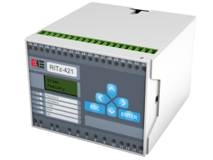
The energising values of RITz-421 relay are currents (IL1, IL2, IL3, and I0) and residual voltage U0 (optional). If any of measured values exceeds setting value (set by user), the relay operates in a manner dependind on configuration. With optional communication interface, the measured currents, binary inputs or outputs, register logs are provided. The PC software provided with relay allows to set the relay, confirm generated signals, graphical display of measured values and browse the register records.
| Rated current In | 1A or 5A |
| Rated voltage U0n | 100V |
| Rated frequency fn | 50Hz |
| Nominal auxilliary voltage Up | 24V DC, 48V – 60V DC, 110V – 230V DC/AC |
| Control voltage Us | acc. to aux. volt. |
| Setting range of threshold current | |
| (0,05÷5)In or (0,2÷20)In for 50/51 protection – def.time char. | |
| (0,05÷0,5)In or (0,2÷2)In for 51 protection – inv.time char. | |
| (5÷500)mA or (0,05÷2,5)A for 50N/51N protection – def.time char. | |
| Accuracy of current inputs | 2,5% |
| Setting range of treshold value of sum of tripped currents counter | (100÷65000)In |
| Setting range of timers | |
| (0÷99,99)s for definite-time characteristics | |
|
|
| Pick-up time | ≤40ms |
| Burden in analog inputs | ≤0,5VA/wejście |
| Burden in auxilliary voltage supply | ≤6W |
| Continous thermal withstand of current input | 2,2In |
| 1 sec thermal withstand of current input | 80In |
| Dynamic withstand of current input | 200In |
| Relay outputs data (S2 – S5) | |
| Max. breaking capacity by U=250V | |
| – resistive load | 0,3A |
| – inductive load of L/R=40ms | 0,12A |
| Max. breaking capacity by U=250V, 50Hz | |
| – inductive load of cosϕ=0,4 | 3A |
| Continuous contact carry | 5A |
| Relay outputs data (S1, watchdog contact) | |
| Max. breaking capacity by resistive load | |
| – AC current | 6A |
| – DC current | 6A/28V; 0,16A/220V |
| Continuous contact carry | 5A |
| Ambient temperature | (268÷313)K/(-5÷40)°C |
| Relative humidity | ≤ 80% |
| Ingress Protection degree | IP40 |
| Weight | 0,8kg |
| Dimensions (height x width x depth) | 75 x 100 x 120 mm |
| Electromagnetic compatibility according to | PN-EN 50263 |
| Insulation according to | PN-EN 60255-5 |
Update your browser to view this website correctly.Update my browser now