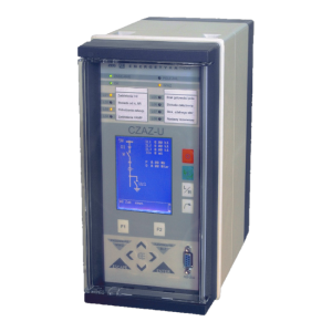
CZAZ-U
Digital protection and control relay for MV power network
Product description
Protection set
| 50/51 |
Instantonous and definite-time overcurrent protection, directional interlock, 2nd harmonic restrained |
| 51 |
definite-time overcurrent protection, 2nd harmonic restrained |
| 51 |
Inverse time overcurrent protection |
| 51N |
Ground fault overcurrent protection, definite-time |
| 51N |
Ground fault overcurrent protection, inverse time characteristic |
| 67N |
Ground fault directional protection |
| 21N |
Ground fault, admittance-based protection |
| 27/59 |
Under and overvoltage protection, two stages |
| 59N |
Residual overvoltage protection |
| 81H/81L |
Over- and underfrequency protection, five stages |
| 62 |
External protection |
| 79 |
Automatic reclose function |
| 55 |
Power Factor control function (only v. 2) |
| • |
Arc flash detector |
| • |
Cable fault detector |
Main features
- Unified and universal hardware and software allowing adaption of the relay to protected objects
- Two realisations of HMI:
- graphic display for visualisation current bay state. It enables to simultaneously display: mimic diagram, several selected measured values and other states. Alphanumeric display also available
- 7” touch screen with resolution of 800 x 480
- specialised bay controller with biult-in logic to provide safe maintance of bay both in local and remote control mode. Proper control functions are coverd by continuous controlling of switch positions and blocking signals from protection functions. The relays cooperate with substation automation system. The functioning of switch control covers:
- Circuit breaker position and charging control – by 3 dedicated binary inputs
- Control voltage supervision
- Trip circuits supervision
- operational and test command for closing the circuit breaker
- operational and trip command for opening the circuit breaker
- position control of disconnector, earthing switch and changeover switch – whatever installed in switchgear bay
- Programmable bay controller with programmable logic which allows to add extra logic circuits and more complex protection circuits (busbar protection or breaker failure logic). Possibility to control bay switches (with proper blocking system of opening and closing commands). Programmable logic is set by simple and user friendly graphic interface:
- 21 binary inputs and 16 logic inputs controlled by communication port
- 14 output relays
- tens of signals generated by biult-in unit logic (pick-ups and trip signals from protection functions, faulty position of switches signals, substation control system signals, trip circuit supervision signals etc.)
- possibility to design user logical circuits and time delays using Boolean operators (AND, OR and NOT), multifunctional timers and other automation functions (eg. technological protection, auto-reclose automation, underfrequency load shedding). Possibility to display logic states on LCD, record in event recorder or send to remote control system
- Set of biult-in bay diagrams or possibility to build user custom bay diagram
- Output circuits allowing to direct control of bay switches, including two trip outputs with trip circuit supervision function
- 8 (CZAZ-U) or 11 (CZAZ-UM) analog inputs (phase currents, phase to phase voltages, residual current, residual voltage – CZAZ-U and -UM and set of currents for differential protection – only CZAZ-UM)
- Measuring of current electrical values (phase currents, residual current, phase or phase to phase voltages, residual voltage, active and reactive power, active and reactive energy in both directions, power factor)
- Recordings of disturbances and events:
- recording of approx. 150 unique events in memory of 500 records
- disturbance recorder saves 8 waveforms and 16 binary signals
- recording of maximum and minimum value of voltage, current or frequency and time of duration of last fault
- trips counter and sum of tripped currents counter
- Visual signalling (LED diodes) of key relay conditions (PWR, OK, TRIP)
- 8 or 16 user programmable LED diodes for signalling other logical values
- system of self control and autotest, signalling improper relay status
- screwless terminals for current inputs, pluggable terminals for other circuits
- communication with PC computer or SCADA system by RS 232/485 port or by fiber optic. Offered communication protocols: MODBUS RTU, MODBUS ASC, IEC 60870-5-103
You need more information?
Contact our Sales Department and talk to our expert about the details.